VR-Forces Capabilities
VR-Forces is a feature-rich simulation tool.
Learn all about VR-Forces by clicking through the tabs below or download the VR-Forces Capabilities document.
VR-Forces Capability Overview – Capable, Usable, Scalable, Flexible, Extensible, Interoperable
VR-Forces comes with a rich set of capabilities that enable you to create, execute, and distribute simulation scenarios. Using its intuitive interfaces, quickly get up to speed and be productive. Build scenarios that scale from just a few individuals in close quarters to large multi-echelon simulations covering the planet. Take advantage of its flexible architecture to configure VR-Forces to run stand-alone on a desktop, in a classroom setting, as a remote simulation server, or embedded into your training devices. Customize it to fit your simulation system or, using the APIs it was built with, extend it to add new capabilities. VR-Forces’ foundation is built on MAK’s interoperable networking technology, so know with confidence that it will connect into your simulation federation.
Capability - Powerful Simulation Engine and Simple Scenario Generation
VR-Forces is a powerful, scalable, flexible, and easy-to-use CGF application that does not require any additional development effort to use or configure.
VR-Forces includes a CGF application comprised of two parts: a simulation engine (often called the back-end) and a graphical user interface (GUI) (often called the front-end) for creating and running simulations. This separation of simulation and control is a key part of VR-Forces’ power and flexibility. Run multiple, interoperable back-ends to distribute the simulation load over multiple computers. Run multiple front-ends to support collaborative scenario development and control.
The VR-Forces front-end allows you to quickly switch between 2D and 3D views. The 2D view provides a dynamic map display of the simulated world. The 3D view provides an intuitive, immersive, situational awareness environment and allows precise placement of simulation objects on the terrain. Quickly and easily switch between display modes or open a secondary window and use a different mode in each one. In either view, you can quickly navigate through the terrain.
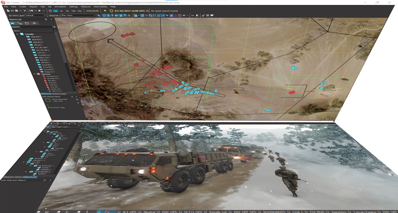
More than just a viewer, the front-end is a scenario creation and editing tool. Populate scenarios with simulation objects and tactical graphics, then assign the simulation objects tasks and plans.
VR-Forces simulates many types of ground, air, naval, and munitions objects, including dismounted infantry. Simulation objects can perform tasks such as moving to waypoints, following user-specified routes, or more complicated tasks like sector search and rescue (SAR) looking for a small ship. Group related tasks into plans for individual entities and units; these plans can then be overridden at run-time if desired. Global plans let you schedule tasks independently of any simulation object. The synchronization matrix allows you to create coordinating plans for multiple entities or units and organize them into phases. All of the simulation object models provided have an extensive set of parameters, which allow you to specify a wide range of performance characteristics.
Usability – Easy, Intuitive, and Collaborative Scenario Setup and Execution
VR-Forces makes the creation and execution of scenarios fast and easy. With a few mouse clicks you can lay-down simulation objects, aggregate them into a command structure, make plans, and send them on missions.
Once the scenario starts, change it on-the-fly by editing plans, assigning tasks, and adding new simulation objects or environmental objects. Change the environmental conditions, force hostility, rules of engagement, or any of the other simulation conditions.
VR-Forces supports collaboration in the creation of scenarios. Multiple users can work synchronously using multiple front-ends that view the same scenario. Or, they can work asynchronously to create portions of a scenario and import them into a master scenario.
Scalability – Large and Small Geographic Areas and Numbers of Simulation Objects
VR-Forces allows you to scale your simulations to cover the entire earth and simulate many thousands of simulation objects simultaneously.
- Use large area geocentric terrain databases to cover any size area of the earth for a simulation. Terrain paging allows VR-Forces to load only the necessary parts of the terrain used for the simulation.
- Use multiple VR-Forces simulation engines as part of a single simulation to spread processing power over multiple computers.
- Model large aggregates as single objects until they enter an area of interest, where they automatically disaggregate into fully simulated individual entities.
Flexibility – Configurability and Deployment Options to Fit your Architecture
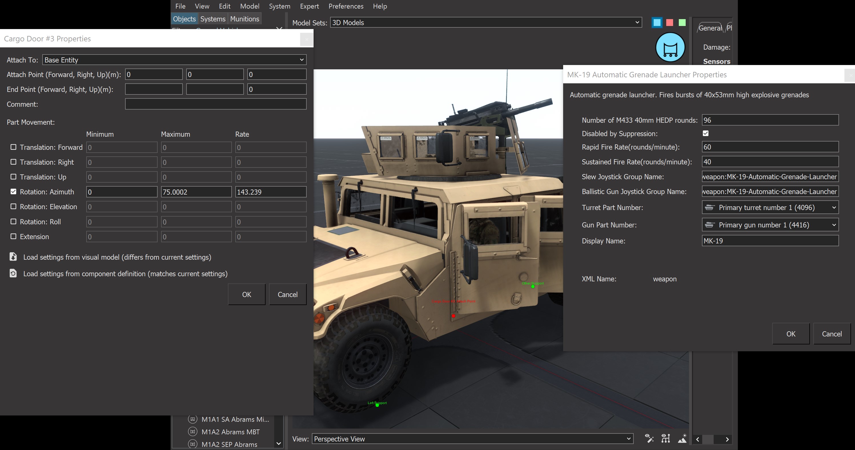
VR-Forces provides the flexibility you need to use it out-of-the-box or to completely customize it meet your specific requirements. It’s easy to set up and preserve your workspace, override default behaviors, and modify simulation object models. Simulation objects have many parameters that affect their behavior. The Simulation Object Editor is an offline tool that lets you manage the specific capabilities of each entity, unit, and tactical graphic. Most VR-Forces users use the editor to:
- Edit basic simulation object parameters (object type enumeration, 2D/3D model, force type, and so on).
- Add simulation models to entities relating to their movement, sensors, weapons, and damage systems and edit all their parameters.
- Add new types of simulation object.
- Assign simulation objects to forces and categories (ground, surface, and so on).
- Choose the 3D model and 2D symbol used to represent a simulation object.
- Configure embarkation slots and ingress and egress points.
- Create simulation object groups for quick insertion of multiple related objects.
- Create unit organizations and formations.
- Edit weapon systems and damage systems. Debug the effect of weapons on specific simulation objects.
Extensibility – Add Specific Capabilities to Accurately Model Your Systems
VR-Forces provides the perfect foundation for customized simulation applications. Because nearly all the functionality can be customized, you don’t need to worry about being locked into default functionality. Its component-based architecture lets you choose which pieces to use and which to implement yourself. And because it is a true toolkit, VR-Forces does not constrain your overall design. It fits into a variety of system architectures.
VR-Forces is highly configurable. You can edit object models and add new simulation objects in the Simulation Object Editor.
VR-Forces’ scriptable tasks enable users with programming skills to quickly develop complex tasks, easily coordinate group behaviors, and script GUI components.
VR-Forces lets you import externally defined data into scenarios, such as MSDL, airspace control orders, and linear, areal, and point objects defined in CSV files.
For those developers who need to extend or customize the VR-Forces application or integrate VR-Forces functionality into custom applications, the VR-Forces Toolkit, a full C++ API, is available. Through this API, nearly every aspect of the VR-Forces simulation engine and GUI is customizable – add, replace, or modify the simulation engine’s vehicle dynamics, behaviors and tactics, damage models, sensor countermeasures, and weapons to suit the needs of your simulation.
VR-Forces is a true simulation toolkit that provides the following C++ APIs:
- Simulation API - Customize or extend the simulation engine, or back-end.
- GUI API - Customize or extend the front-end graphical user interface.
- Remote Control API - Send control messages to the back-end of VR-Forces from other applications.
- Terrain API - Read, write, and query terrain databases.
- Plug-in API - Add functionality to VR-Forces or modify existing functionality without rebuilding the core VR-Forces applications.
Interoperability – Interoperates with Your Networked Simulation System: DIS and HLA
VR-Forces is built on top of VR-Link® and takes advantage of VR-Link’s protocol independent classes, making VR-Forces fully compliant with DIS, HLA 1.3, HLA 1516 (SISO DLC version of HLA 1516-2000), and HLA Evolved (HLA 1516-2010). VR-Forces has built-in support for the RPR FOM, but like other MAK tools, it is FOM-Agile, allowing it to be tailored to other FOMs through VR-Link's FOM-Mapping architecture.
Levels of Modeling and Simulation – Aggregate and Entity Level
VR-Forces simulates at both the Aggregate Level and the Entity Level.
With aggregate-level simulation, commanders control the flow of engagements while the models consume and replenish resources, as well as monitor how the engagements affect simulation object resources. Entity-level simulation provides specific control of individual vehicles, munitions, human characters, even animals. It is useful for training operators as well as team tactics, techniques, and procedures.
Aggregate-Level Simulation
VR-Forces provides aggregate-level simulation capable of modeling the operational tempo (optempo) of large area/theater level missions overseen by command staff level officers. This is useful in both training staff officers, as well as stimulating Command and Control systems (for example, C2, C4I, C4ISR, and Mission Command systems).
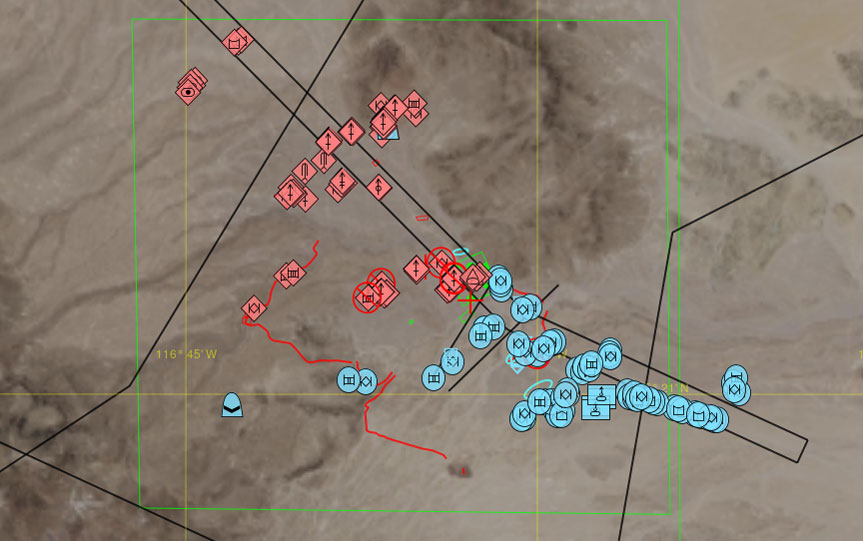
Aggregate-level simulation models include:
- Aggregate Combat Models – Aggregate combat models determine attrition on both the attacker and the target based on combat power, weapons system, ammunition available, vulnerability, range, attack and defense postures, and so on.
- Combat Engineering Models – Combat engineering models create and breach structures in the environment that affect mobility, combat power, sensing, and vulnerability. Combat engineering objects include: roads, bridges, ditches, obstacles, strong points, fortifications, bunkers, minefields, flooded areas, unexploded ordnance, and so on.
- Air Combat Models – VR-Forces models air bases that can prepare, launch, and recover air missions.
- Electronic Warfare Models – EW models affect the units that are susceptible to electronics for operations, such as sensors, guidance systems, communications, and force tracking systems.
- Movement Models – Movement models determine how the aggregate units move across/above/below the terrain. The locations of aggregate subcomponents are abstracted away, and represented by ‘Posture’ which determines size and speed of the aggregate. Movement speed is limited by: terrain slope, restricted movement areas in terrain, combat engineering objects, precipitation, protective gear (MOPP) status, and overlap with other units.
- Sensor Models – Sensor models determine the level of information known about sensed objects. This combat identification level has four stages: detection, classification, identification, and full knowledge. Sensors’ ability to detect are affected, in part, by the signature of objects. Simulation objects have signatures that determine their susceptibility to detection in each sensor domain, such as visual, radar, infrared, and sonar.
- Weather Models – Weather models affect simulation objects based on wind, visibility, precipitation, cloud cover, sea state, and terrain and ocean characteristics. VR-Forces models fog, dust, mist, haze, smoke, sandstorms, and volcanic ash. Snow and rain accumulate on the ground. Rain can form puddles and snow can blow in the wind.
- NBC Models – NBC models simulate nuclear, biological, and chemical contamination effects on unprotected units. The Mission Oriented Protective Posture (MOPP Status) of the units is used by the combat models to affect operational tempo.
- Intelligence Models – Intelligence models determine when sensed units are reported to the command and control systems. A master scenario event list (MSEL) is used to present situational information to the simulation operators. Events can be triggered by time, other events, or manually. Situational events can contain text, audio, images, or video. Events are available on the network and can be sent to external role player systems.
Entity-Level Simulation
VR-Forces simulates people and vehicles (a.k.a. platforms) in all physical domains (ground, sea, sub-surface, air, space), as well as the interactions among simulation objects.
All simulation objects have a few things in common: access to the virtual environment (network, terrain, and so on.), basic kinematic state information (position, orientation, velocity); a resource manager for managing consumable resources (fuel or ammunition), lists of sensor, controller, and actuator components, and the ability to be positioned in a military organization.
Physical simulation objects understand how they are supposed to interact with their environment. Their behavior is affected by that environment as determined by these models:
- Combat Models – Entities have weapons systems, such as small arms, main guns, missile systems, and bombs. Entities use ammunition tables to determine what types of ammunition to use against opposing forces. Damage tables determine their response to direct hits and indirect fire.
- Movement Models – Movement models determine how the entities move through the simulated world, taking into account various terrain, environment, and simulation object capabilities.
- Sensor Models – Sensor models determine the level of information known about sensed objects. This combat identification level has four stages: detection, classification, identification, and full knowledge. Sensors have sensitivities that determine their ability to detect and detectable objects have signatures that determine their susceptibility to detection in the different sensor domains: visual, radar, infrared, sonar.
- Weather Models – Weather models affect simulation objects based on wind, visibility, precipitation, cloud cover, sea state, and terrain and ocean characteristics.
- Intelligence Models – A master scenario event list (MSEL) is used to present situational information to the simulation operators. Events can be triggered by time, other event, or manually. Situational events can contain text, audio, images, or video. Events are available on the network and can be sent to external role player systems.
- Communications Models – The communications model is used to send messages between simulation objects with options to model communication degradation by the network infrastructure.
Simulating Behavior
VR-Forces is a flexible framework for simulating objects and their interactions with the environment and other simulation objects.
These behaviors give VR-Forces simulation objects a level of autonomy to react to the rest of the simulation on their own. This saves you from having to script their behavior in detail. The autonomous behaviors include:
- Using sensors to detect other simulation objects.
- Attacking enemy simulation objects on contact, based on the current rules of engagement.
- Sending and receiving spot reports through the simulated radio networks.
- Entity activity like "wander about" and "flee from something".
- Identifying obstructions to movement and moving around them.
- Advanced navigation using Autodesk Gameware Navigation software.
Entities and Units
VR-Forces simulates at the Entity Level or the Aggregate Level depending on which simulation model set (SMS) you use. Entities or units form the basic units of the simulation and are composed of models that collectively represent units at all echelons, vehicles in all domains (air, land, sea, space), munitions, cultural objects, and lifeforms.
The specific capabilities of entities and units are defined within entity definitions, which are organized within Simulation Model Sets (SMSs). VR-Forces comes with two pre-defined simulation model sets: an aggregate level SMS, which defines aggregate level simulation object models and an entity level SMS, which defines entity level models (platforms, humans, and munitions).
Entities can function independently or collaboratively, such as:
- Embedding – This is the ability for a host entity to deploy other types of entities that it might typically carry. (Example: a ship that can deploy helicopters to dip sonobuoys.) Embedded entities simplify the planning of scenarios by allowing users to ignore the embedded entities until that part of the scenario where they need to be deployed. Compared to embarked entities, scenario developers do not have to create and embark the entities during scenario creation and the deployment and recovery process can be automated. Embedded entities also increase network performance by not sending out messages until they are deployed and independent of the host entity.
- Embarkation – Embarkation is the ability for one entity to embark on (or attach to) another entity. Embarkation ensures that closely coupled entities, like a person driving a car, or the helicopter on the deck of a ship, or a missile loaded onto an airplane, all share a common frame of reference.
- Entity Aggregation – Different than aggregate-level simulation, entity aggregation is a way to organize individual entities into echelon structures so that single commands can be carried out by multiple entities. In addition, units can provide information about their echelon structure, location, and health. The Behavior Engine allows some units to perform complex, coordinated tasks.
- Simulation Object Groups - Simulation object groups allow you to create a configuration of simulation objects and tactical graphics that can be added to scenarios like individual simulation objects. They are not tied to a terrain location, so they are available to any scenario. They can include plans and scripted tasks, so that they are analogous to mini-scenarios that you drop into a larger scenario.
Simulation Models
Simulation models define and implement the capabilities of the simulation objects within the simulation. The specific configuration of a simulation object defines which models apply to it. Let's have a look at the models in VR-Forces.
Behavior – Movement
Movement models determine how simulation objects move through the simulated world.
- Dynamics Models – These are built into VR-Forces simulation objects that use an actuator/controller paradigm to "steer" through the virtual world. When you task a simulation object to move, it’s the dynamics model that defines how. See Defining and Controlling Behavior for the various ways of tasking simulation objects.
- Mobility Models – Mobility Models affect—and usually limit—the capabilities of the dynamics model defined for simulation objects based on the conditions of the terrain and atmosphere. For example, a ground vehicle’s mobility is degraded when driving over mud, and stopped completely in deep water.
- Hi-Fidelity Dynamics Models – VR-Forces comes with a full library of vehicle dynamics models for air, land and sea. Some of MAK’s customers develop higher-fidelity dynamics models for a particular vehicle in their domain. You can develop your own dynamics models and use them within VR-Forces. MAK also has partners who provide high fidelity dynamics models:
- RT Dynamics provides high fidelity rotor craft and fixed wing aircraft.
- CM Labs provides high-fidelity ground vehicle models.
- Animated Movement – A particularly high-fidelity way to move simulation objects is to provide them a predefined animation sequence to follow. This is an important technique for engineers who develop extremely high-detailed engineering models of vehicles or munitions. Users of MATLAB SimuLink can export the results of a dynamics simulation and use that animated sequence to control the motion of a simulation object. This is useful for visually validating the engineering models and for communicating the value of the models within an operational context.
- Embarked Motion – When one simulation object is embarked on another, the embarked simulation object moves with the host simulation object. For example, a person in a car moves because the car is moving.
Civilians and certain other humans can open and close car doors when embarking on and disembarking from cars that support this feature.
- Formations – Out-of-the-box and user-configured formation types define disaggregated unit movement. As units are commanded and move to a waypoint or along a route, subordinate simulation objects maintain the proper position within the formation. If a member is destroyed, other simulation objects move to fill the gap.
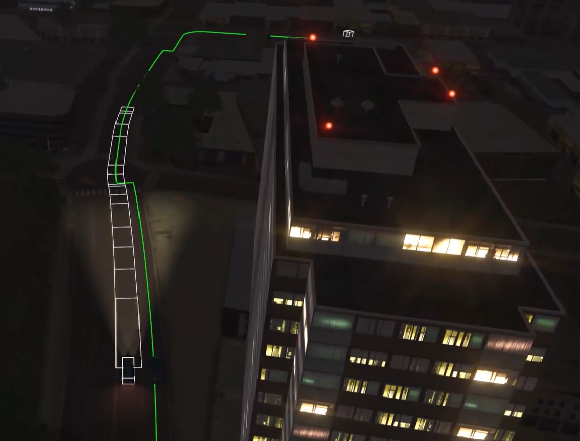
- Path Planning – When simulation objects move, they can take the most direct route to the destination, or use a path-planning algorithm to intelligently generate a route. If you select path planning, VR-Forces takes roads, rivers, and other feature data into account, to generate a route that makes sense. If you want to define precisely what route a simulation object should take, create a route, then task the simulation object to move along that route. VR-Forces also supports advanced path planning using AI techniques.
Advanced Navigation
VR-Forces uses Autodesk Gameware Navigation to extend the path planning and movement capabilities of lifeforms and ground platforms.
- Artificial Intelligence (AI) Path Planning – Uses the terrain topology and typography to figure out how simulation objects should move to achieve their tasks, without the need for any manual tagging or marking of the terrain.
- Motion for Humans – Finds paths for people that can go through buildings, up and down stairs, along roads, and through narrow spaces – essentially anywhere a person can go.
- Motion for Ground Vehicles – Uses the terrain and road networks to find paths for ground vehicles. Vehicles are not limited to the roads, but the user has control of whether they prefer the roads.
- Automatic Regeneration of Navigation Data – VR-Forces automatically regenerates navigation data in response to changes to dynamic terrain.
The Appearance of Movement
Since high-fidelity dynamics models are computationally expensive, VR-Forces uses techniques that enable users to choose lower fidelity dynamics and adjust the appearance of motion within the visualization of the simulation objects.
- Smoothing – Smoothing is a method of ensuring that transitions from a simulation object's dead-reckoned position to its actual position are not so abrupt as to be visually disconcerting.
- Ground Clamping – Ground clamping allows the simulation object’s position to match the terrain even if the positions communicated over the network drifted slightly off the terrain.
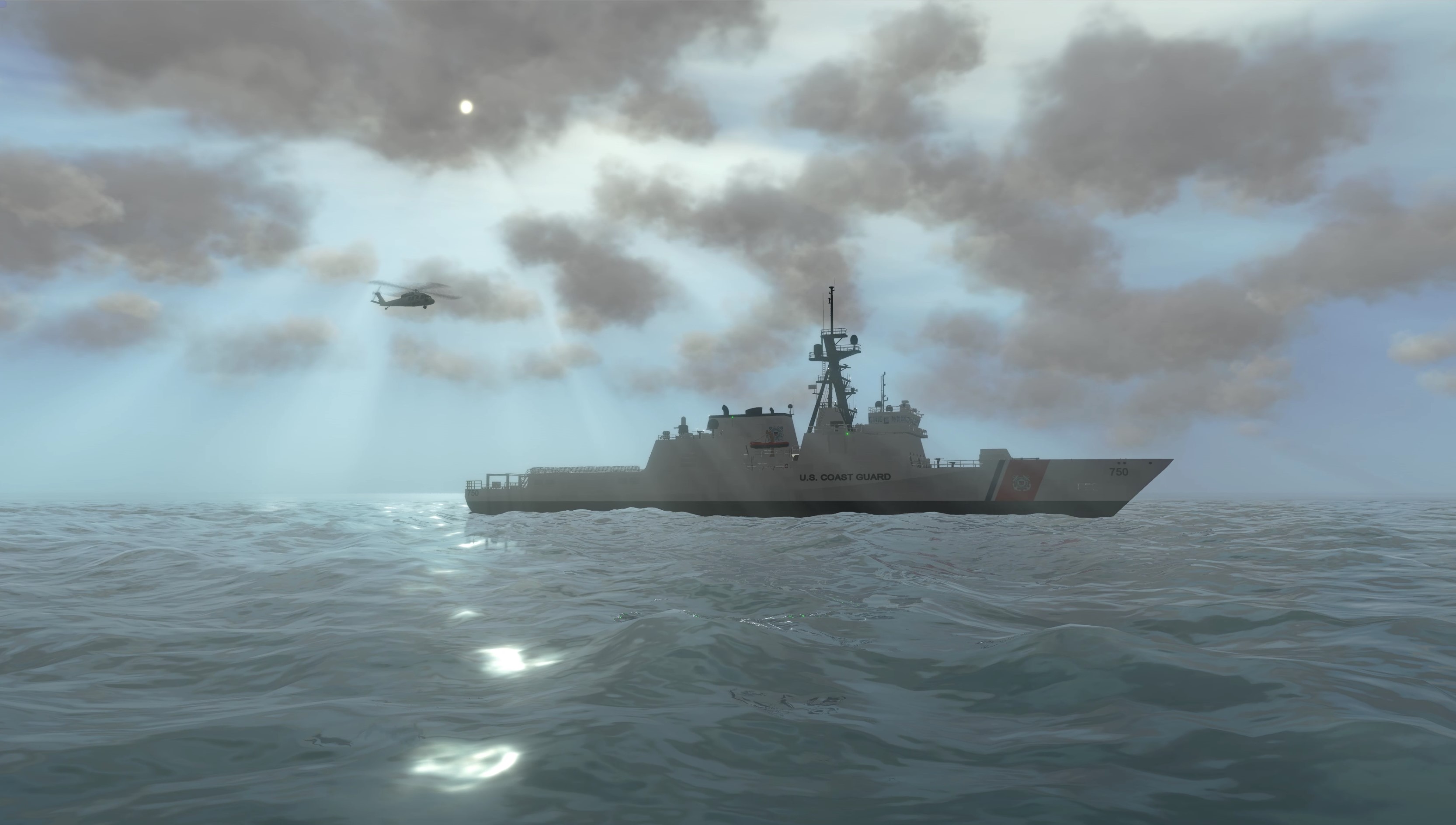
- Ship Rocking – Ship rocking allows the visual system to alter the pitch and yaw of an entity to match dynamic ocean models in the visualization. This enables the simulation engine to limit its dynamics on the horizontal motion of the entity.
Sensor – Detection
Sensor Models determine the level of information known by a simulation object about the other simulation objects in the simulation.
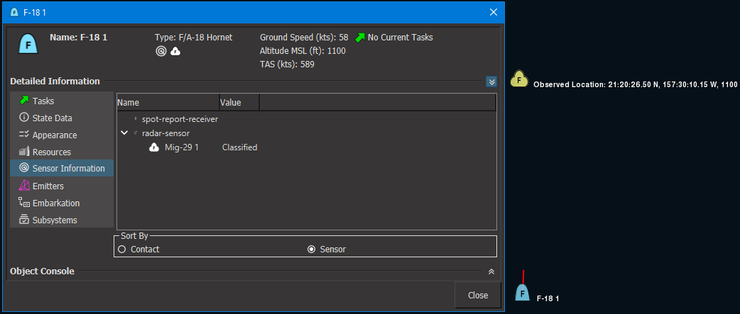
- Sensor Domains – Sensors have sensitivities that determine their ability to detect and detectable objects have signatures that determine their susceptibility to detection in the different sensor domains: visual, radar, infrared, sonar, and EW Simulation objects can visualize sensor contacts using sensor contact lines.
- Combat Identification Level – This is a measure of how much a simulation object knows about other simulation objects. The stages of detection, classification, identification, and full knowledge provide a straightforward way for other models to alter behavior based on the perception of each simulation object.
Sensor Views
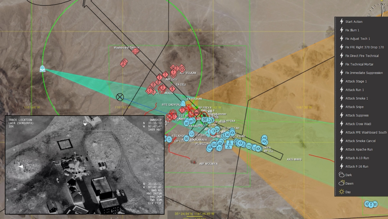
VR-Forces can display the view from gimbaled visual sensors, such as a camera on a UAV. The view is displayed in an inset window that has information about the observer mode and area being viewed. The window has its own observer and you can change the observer mode in the view. Each sensor view has a control panel that you can use to move the sensor, change its aim, and zoom in and out.
Combat – Damage
Aggregate Combat Models, used in aggregate-level simulation, determine attrition on both the attacker and the target of the attack based on combat power, weapons system, ammunition available, vulnerability, range, attack and defense postures, and so on.
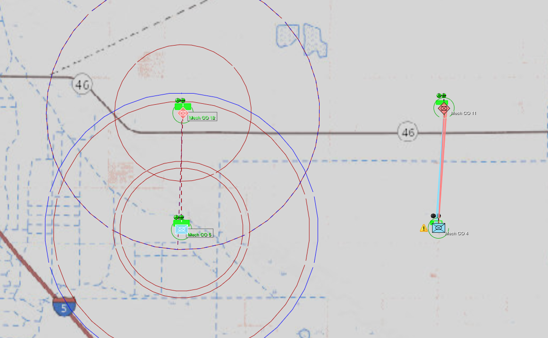
Combat models, used in entity-level simulation, engage by sensing other simulation objects and using their weapons against opposing forces.
- Weapons – VR-Forces supplies a large collection of pre-configured direct and indirect fire weapon systems for the models defined in the default simulation model sets. These include: guns, bombs, rockets, missiles, laser designator systems, illumination flares, and so on. Combat models know which types to deploy against which types of opposing simulation objects.
- Defensive Systems – Combat models deploy counter measures to reduce the probability of a hit by weapons fire.
- Damage Models –As directed by the distributed simulation protocol, VR-Forces sends messages to the network to tell other simulation federates what kind, where, and with what force the munitions have detonated. It is up to each simulation to compute the effect of the detonations. VR-Forces computes the effects of all detonations on simulation objects that it manages.
- Hostility Model – VR-Forces maintains a matrix of multiple force affiliations that indicates which forces are friendly, neutral, and hostile to other forces. This matrix is used by the combat models to determine which simulation objects to engage, or whether to engage them at all. Simulation objects can change force allegiance during the simulation, making for very interesting and challenging training situations.
- Rules of Engagement – Simulation objects use rules of engagement to determine if they will engage opponent simulation objects or hold their fire. Rules of engagement can be changed dynamically during the simulation.
- Combat Engineering Models – In aggregate-level modeling, combat engineering models create and breach structures in the environment that affect mobility, combat power, sensing, vulnerability. Combat engineering objects include: roads, bridges, ditches, obstacles, strong points, fortifications, minefields, and so on.
Environment – Weather – Contaminants
The environment, the weather, and contaminants in the environment all affect the outcome of the simulations.
- Electronic Warfare Models – These affect the other models that are susceptible to electronics for operations, such as sensors, guidance systems, communications, and force tracking systems.
- Weather Models – Weather models affect the other models based on: wind, visibility, precipitation, cloud cover, sea state, temperature, and terrain and ocean characteristics. VR-Forces models fog and sandstorms. Snow and water accumulate on the ground and form puddles.
- Contaminants Models – These simulate nuclear, biological, and chemical contamination effects on unprotected units. (aggregate level simulation only)
Communications – Intelligence
Communications models send messages between simulation objects, allowing them to coordinate on mission activities and trigger events. Intelligence models determine when sensed units are significant and send reports to the command and control systems.
- The Master Scenario Event List (MSEL) – is used to present situational information to the simulation operators. Events can be triggered by time, simulation events, or manually. Situational events can contain text, audio, images, or video. Events are available on the network and can be sent to external role player systems.
- Fog of War – VR-Forces uses the combat identification level of simulation objects to present a tactical map of them. By default, VR-Forces shows ground truth for all objects. That is, it shows all objects known on the simulation network, and it shows them in their actual simulated locations. However, in the real world, combatants often do not know the location of the opposing forces, or even that of friendly forces. They only know what has been reported to them from the field via spot reports. The VR-Forces spot report feature sends spot reports for simulation objects that have been sensed and the plan view display can be configured to show the reported positions. VR-Forces can also increase the transparency of spot report icons to simulate the degradation of the information they represent over time.
- "Perfect" Communication Model – VR-Forces includes a default "perfect" communication model. This communication model simulates radio traffic in a very simple way. Radio messages always reach their intended destination; as long as the destination is on a reachable network, messages are all passed instantly.
- "Imperfect" Communications Model – VR-Forces communications models are capable of connecting to an external communications effects server to determine when, or if, to deliver radio messages.
MAK’s partner Scalable Networks offers a communications effects server that models all the nodes in the communications network and determines which simulation objects are able to communicate with each other, and how long it takes a message to be transmitted from the originator of the message to the receiver of the message.
- Identify Friend or Foe (IFF) – IFF models the recognition of electronic signals associated with simulation objects to identify their force allegiance.
- Link-16 Communications – VR-Forces is Link 16 compatible and can be used to stimulate Link 16-based operational systems.
Resources - Health
Simulation objects in VR-Forces track their current quantities of various resources, such as ammunition and fuel. The availability of these resources affect the simulation models as the scenario executes. The aggregate level simulation tracks additional attributes such as the current equipment and personnel, as well as the abstracted aggregate attributes like overall health. This information can be established as pre-conditions (order of battle), can be set interactively during the simulation, and is affected by the activity of the simulation models as the simulation plays out.
Productive/Flexible Workflow – Users, Modelers, and Developers
VR-Forces has a three-tiered approach to how it’s used:
1) “Users” can create and run scenarios with the installed application,
2) “Modelers” can configure the system to add content and customize it for their users, and
3) “Developers” can extend it or use it to build custom applications.
User – All the Capabilities to Use VR-Forces Out-of-the-Box
VR-Forces is ready to use from the moment you download and install the software. It has all the features you’ve come to expect in sophisticated simulation software: a robust system of scenario planning, multiple ways to view the environment in which you are developing your scenarios, intuitive and comprehensive user interfaces, and even the ability to control time itself.
Defining and Controlling Behavior
VR-Forces uses the concept of a scenario to define and control the behavior of the simulation objects within a simulation exercise. There are many ways to set up scenarios and plan simulation object behavior. A scenario can define simulation object starting positions and simulation object tasking (order of battle); users can interact with the scenario while the simulation is running; multiple people can collaborate on the scenario definition; the simulation object and those participating in a distributed exercise can trigger events that affect the simulation’s outcome.
- Plans – Each simulation object can have a plan defined within the scenario. A plan is a collection of tasks to perform and the definition of conditions under which the plan may vary. The simulation object tries to execute this plan. Plans can be edited, saved, and reused repeatedly. This is useful for creating training curricula and for setting up scenarios for experimentation. Plans can be overridden by assigning individual tasks to the simulation object running the plan.
- Tasks – VR-Forces has a built-in set of tasks and “set data requests” (commands that cause a simulation object to change a state variable immediately) that you can assign to simulation objects in plans or dynamically as the scenario unfolds. Tasks include actions like move to a location, move along a route, follow another simulation object, fire for effect, aircraft takeoff and landing, wait, and so on.
- Triggers – Plans use triggers to interrupt its task sequence in response to specific events that you want simulation objects to react to, regardless of what they are doing at the time. Triggers can be based on the presence of simulation objects in specified areas, on receipt of text messages, on simulation time, or for other reasons. For example, the detection of an simulation object by a sensor model can cause a trigger to fire.
- Scripted Tasks and Sets – Add to the built-in tasks and sets provided with VR-Forces by writing scripts using the Lua scripting language. The Lua interface gives you access to all built-in tasks and sets plus geometric data and simulation object state data that is not accessible in plans. Scripts, whether created by the engineers at MAK or by users, can be added to the task and set menus and used in plans just like the built-in tasks and sets.
- Reactive Tasks – Scripted tasks can react to conditions in the simulation. Reactive tasks function similarly to triggers, but are independent of plans and due to the flexibility of Lua scripting, they can be more versatile than triggers. Multiple reactive tasks can be assigned with given priorities to enable simulation objects to react to complex situations.
- Behavior Sets – Scripted tasks can be organized into behavior sets and applied to simulation objects as a function of their “force” value. In this way, sets of behavior can be designed to support the doctrine of different forces so that, like object types, they will behave differently according to their doctrine.
- Path Planning – The path planning feature provides intelligent movement for human characters and ground vehicles. Movement tasks take the terrain, road networks, and sensor perception into consideration when planning navigation paths.
- Pattern of Life – Quickly populate scenarios with purposeful human behavior that does not require entity-specific planning. Create individual entities that automatically move through the world to a random destination or that execute custom plans. For more information about pattern of life, read our white paper.
- Crowd Behaviors - Create crowds and assign them tasks such as wander, gather around a location, or protest in front of an entity.
- Simulation Object’s State – Set aspects of a simulation object’s state, such as heading, speed, formation, altitude, identify friend or foe (IFF), electromagnetic emissions, target, force affiliation, and many more.
- Checkpoint and Snapshot Simulation State – Save the current state of the scenario as a checkpoint either automatically at specific intervals or manually. Each checkpoint is a complete save of the simulation in its current state. Once you have saved a checkpoint, you can run the scenario from that point by loading the saved checkpoint. Snapshots let you quickly roll back your scenario in increments as small as one second to replay from a point of interest. Snapshots are stored in memory, which decreases loading time and eliminates the overhead of saving to disk.
- Scenario Collaboration – VR-Forces enables collaborative creation of scenarios. Multiple users can work simultaneously using multiple GUIs (front-ends) that operate on the same scenario. Or, they can work independently to create portions of a scenario and later merge then together with the Scenario Merge tool.
- Interactive or Batch Runs – Scenarios can be run interactively or without interaction (batch mode) for Monte Carlo simulations. Command-line options let you create startup scripts for easy repetition of custom configurations.
- Global Plans – Global plans run independently of the simulation objects within a scenario. They can use simulation time or events within the scenario to trigger all sorts of actions. They can create and delete simulation objects, control objects, and tactical graphics. Global plans can include commands for simulation objects that do not exist yet in the scenario.
- Synchronization Matrix – Allows you to work with multiple entities or units and add coordinating plans and tasks that are laid out in a series of phases. It makes it easier for you to create and manage scenarios where there is synchronization between entities or units.
Viewing Modes
The visual components of VR-Forces are built with the VR-Vantage Toolkit. This means that your CGF has a full suite of visualization capabilities that can be accessed at run-time without ever having to leave the primary VR-Forces application.
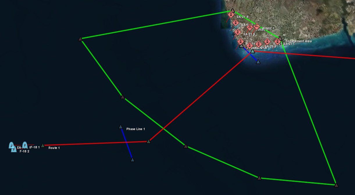
- Tactical Maps (PVD mode) – Whether you want 2D tactical map views that can show raster graphic maps or top-down views of the terrain database, it’s your choice. All the functionality you need to create and run a scenario can be found in the 2D plan view. Create simulation objects, give them tasks, and control the simulation time. simulation objects are shown with MILSTD 2525b symbology but can be replaced with alternative symbology. You can add tactical and informative graphics to make the most productive user experience possible.
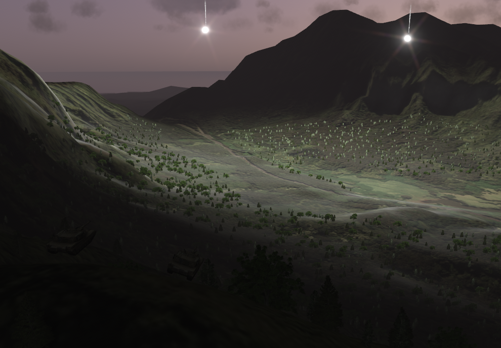
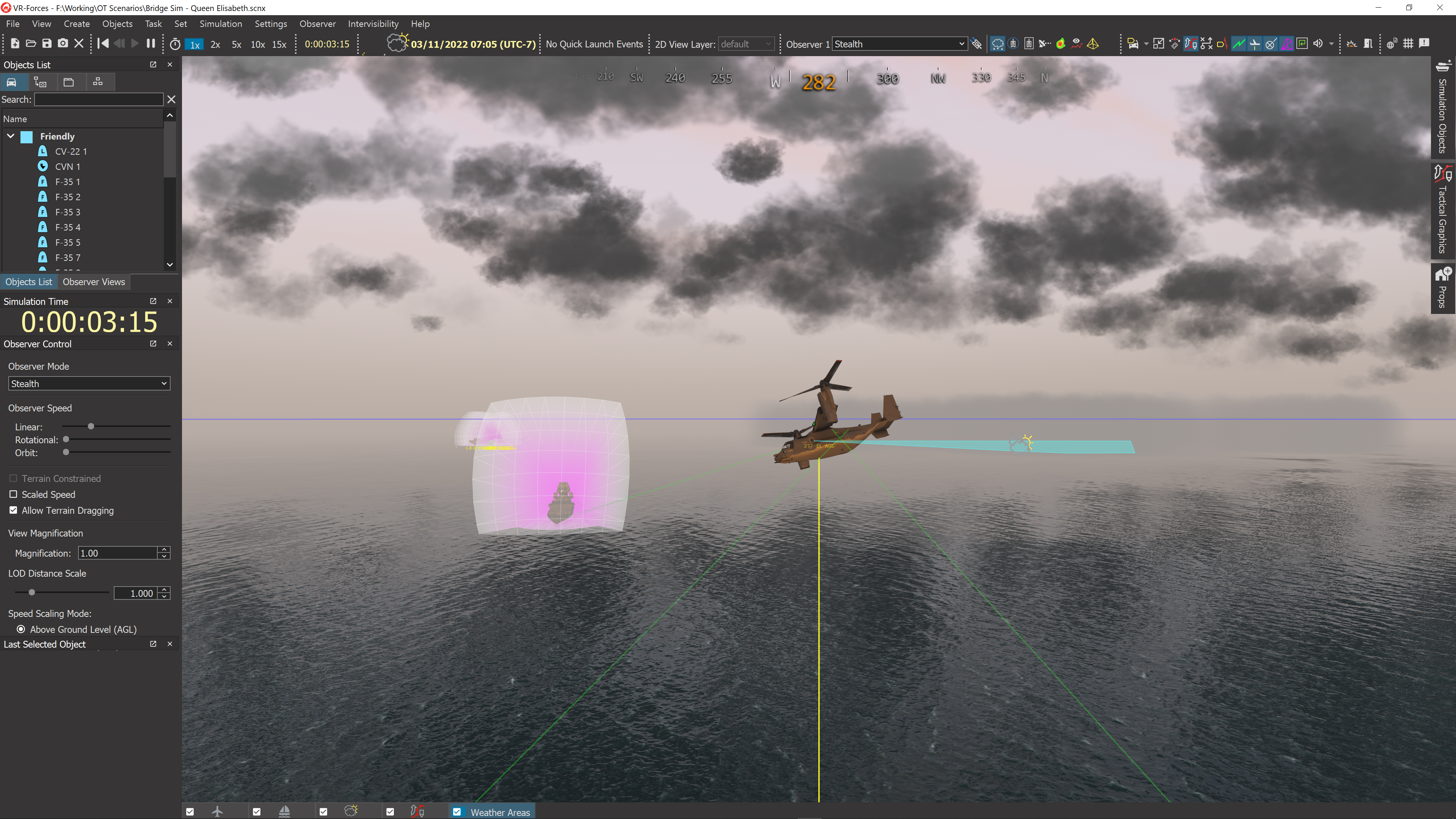
- Realistic 3D views (Stealth mode) – This mode provides a three-dimensional view that mimics what simulation users see in their training devices and lab simulators. This view allows you to precisely place entities into the scene without the need for a second application to view the 3D scene while you create a scenario. This view is particularly useful when creating scenarios in urban environments that require you to place entities inside of structures or at precise street locations.
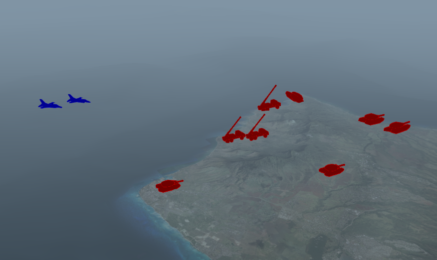
- Symbolic 3D views (XR mode) – XR mode exaggerates the scale and contrast of all the entities and adds 3D graphical information to make 3D, information-rich views that have characteristics of both the 2D tactical views and the Stealth views.
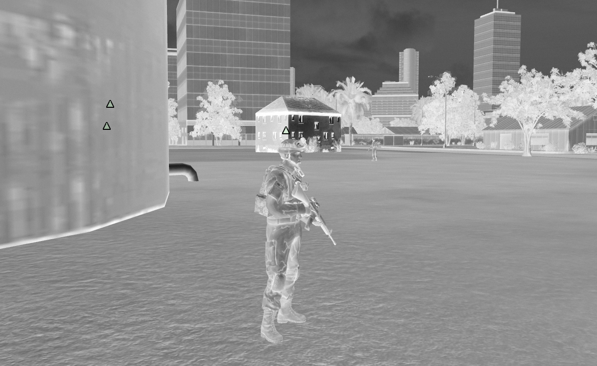
- Sensor Views (EO, IR, NVG modes) – Sensor views mimic the view a simulation user would get looking through a sensor.
Intuitive User Control from the GUI
The graphical user interface (GUI) provides extensive control over the creation and management of the simulation scenario and all the simulation objects within. Create and remove simulation objects and move them arbitrarily about the terrain. Creating multiple simulation objects of a given type is just a matter of selecting the simulation object in the Simulation Objects Palette and clicking on the terrain. You can copy and paste simulation objects with their current state and plan.
Watch the simulation objects as icons on the map, in the 3D views, and as items in the configurable GUI panels. Pan and zoom the 2D views and fly through the 3D views. Navigate the terrain using game-like keyboard controls and the mouse. Attach to simulation objects and follow them around. And save the views in a file to recall later.
You can access commands through a main menu, through keyboard accelerators, and through context-sensitive popup menus. Undock toolbars and place them anyplace on the desktop, as you choose which toolbars you want visible and which hidden. Set feature options on multi-paged dialog boxes, and quickly toggle the most-used using menu options, toolbars, and keyboard shortcuts. Your GUI settings are saved automatically so that you can set up your preferred work environment once and then return to it every time you load VR-Forces.
You have complete control of the simulation environment from the GUI. Save the scenario for later execution, or run it right now. Play, pause, or rewind the simulation clock to control the action. If you are using multiple back-ends, you can specify the simulation engine on which a simulation object will be simulated. The Echelon View lets you view simulation objects by force type, expand and contract the display of units on the map, and even display ghosted views of the simulation objects in collapsed units.
Visual and Analytical Information
Visuals in VR-Forces are more than just pretty pictures – graphics are used to present information about what is happening in the simulation and are tools to help control the flow of the action. GUI panels provide access to all the internal information about the simulation while you are setting up the scenario and while it’s running.
- Control Objects – Control objects are graphical objects that you draw on the terrain and organize within tactical overlays that affect the simulation. Waypoints, routes, phase lines, areas, and obstacles can be used in tasks and plans. Simulation objects know about them and can move to them, along them, through them, and in the case of obstacles, avoid them. You can edit the vertices of graphical objects using your mouse or dialog boxes. You can also add additional vertices to the objects. You can edit the characteristics of tactical graphics at run time manually, or using set data requests in plans.
- Tactical Overlays – Analogous to clear film overlays that you might layer over a map, tactical overlays allow you to group control objects into meaningful sets. Tactical overlay objects are not just pixels on the display. They are first-class objects that are published via HLA or DIS. If you want to provide greater interaction between simulation objects and tactical graphics than is provided by VR-Forces out-of-the-box, they are fully accessible by custom vehicle model code.
- Simulation Object Icons and 3D Models – Since you can display the simulation on both 2D maps and within 3D scenes, VR-Forces provides a rich library of 2D map symbols and 3D models to represent your simulation objects.
- Fire & Detonate Lines – During engagements, VR-Forces displays fire and detonation lines, which show you the source and target of munitions fire. Animations highlight detonations and add to the experience with fire and smoke.
- Object Information Panels – Information panels present the internal state information for the selected simulation objects, including: task status; position, appearance and state information; sensors, weapons, and resources status. Essentially all the state data from all the models associated with a simulation object can be inspected using object information panels.
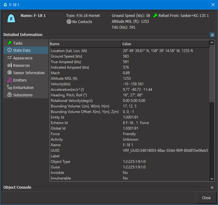
- Simulation Object Labels – On-screen simulation object labels present simulation object state information. In plan view mode, you can customize what information is shown.
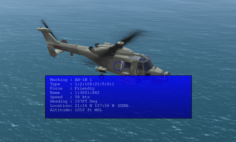
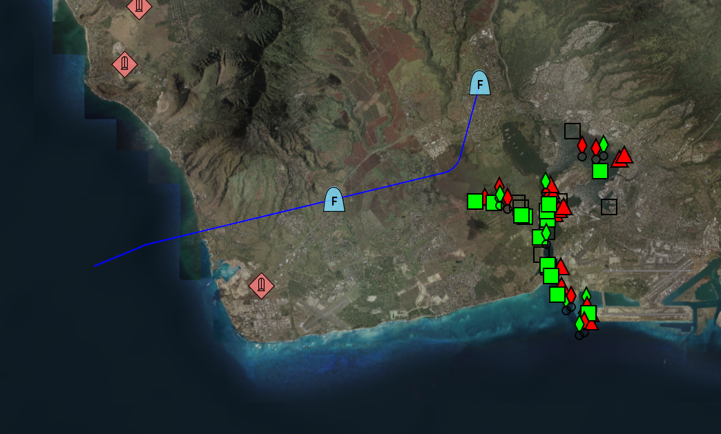
- Track Histories –Track histories display the path a simulation object has followed to arrive at its current position.
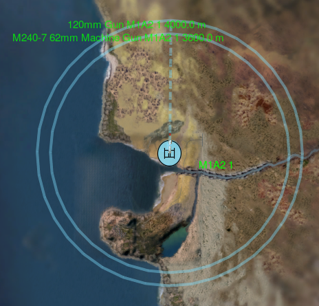
- Threat Range Rings – Range rings graphically show the area in which the simulation object’s armaments are effective.
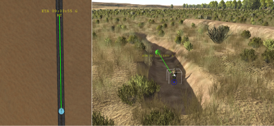
- Task Visualization - Visualize the path a simulation object is taking as it carries out a task.
- Tactical Smoke – Visualize the tactical smoke used to obscure visibility by sensors.
- Electromagnetic Emissions – Electromagnetic emission volumes identify the on/off state of emitter systems on simulation objects.
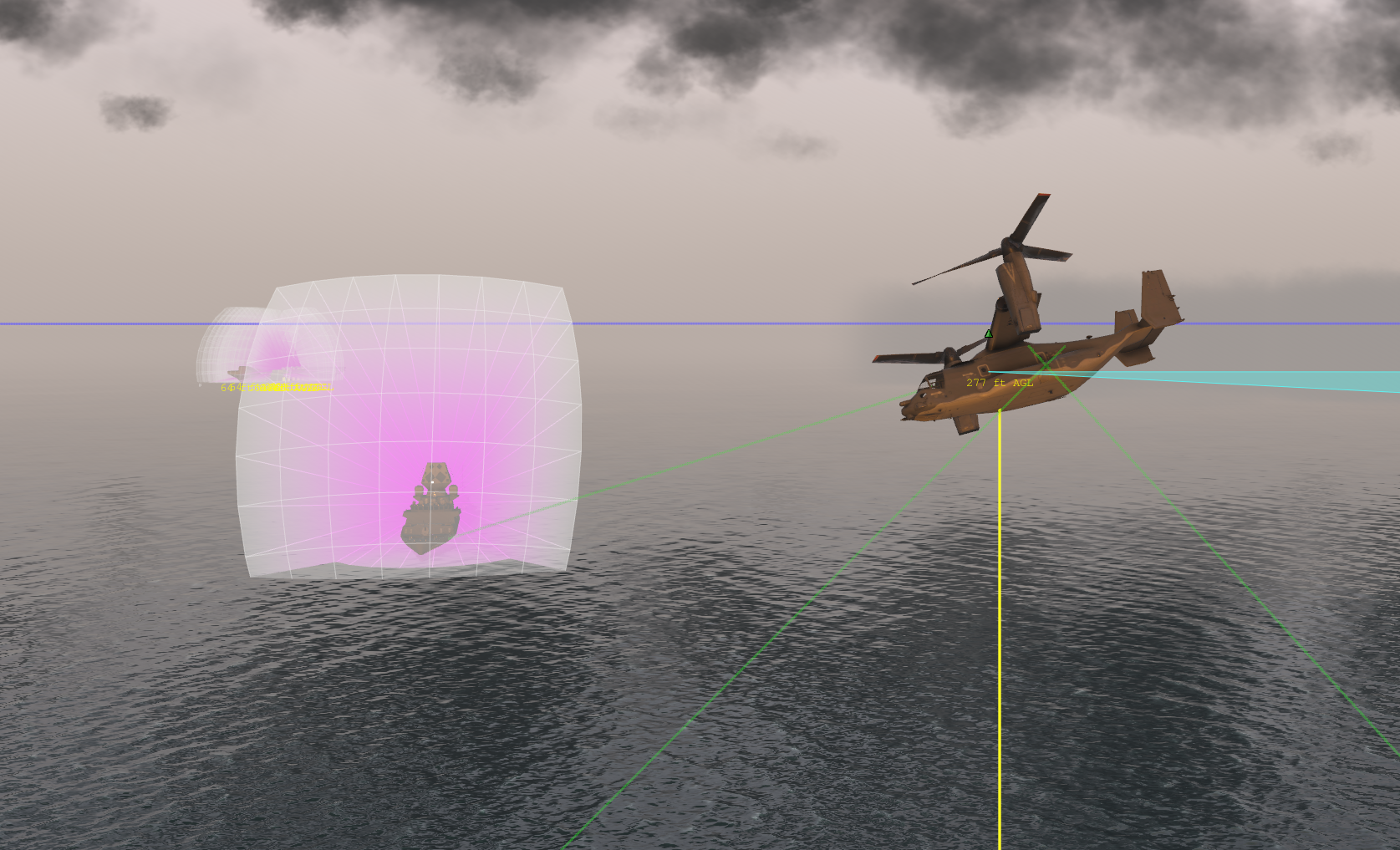
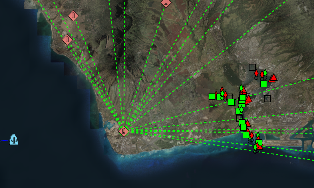
- Radio Comm Lines – When simulation objects send radio communications, these lines connect the sender with the receivers of the message. These lines work on flat maps and global 3D worlds.
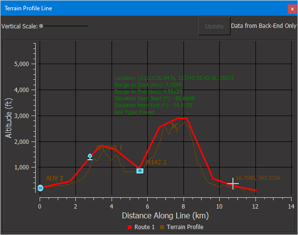
- Terrain Profile Graphs – The graphs plot lines and simulation objects against the height of the terrain to show relationships that are not apparent in plan view mode.
- Intervisibility lines & fans – Intervisibility (line-of-sight) lines and fans help you understand what simulation objects can and cannot see.
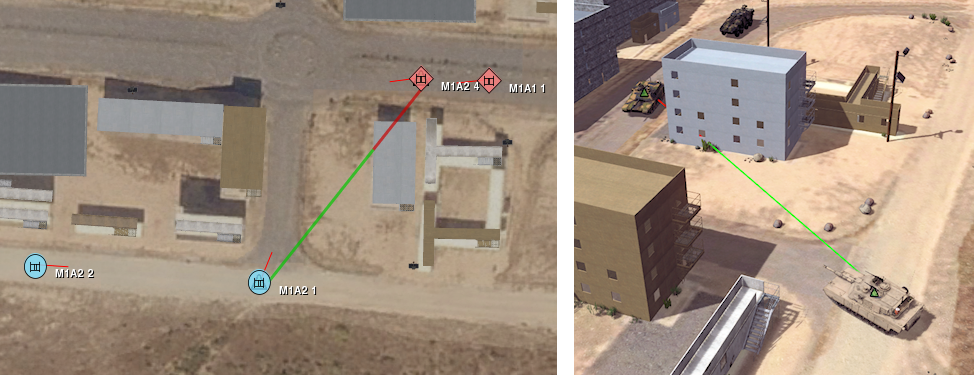
- Sensor Contact Lines - Intervisibility lines show what is visible by line-of-sight. Sensor contact lines show contacts that are actually made using all sensors.
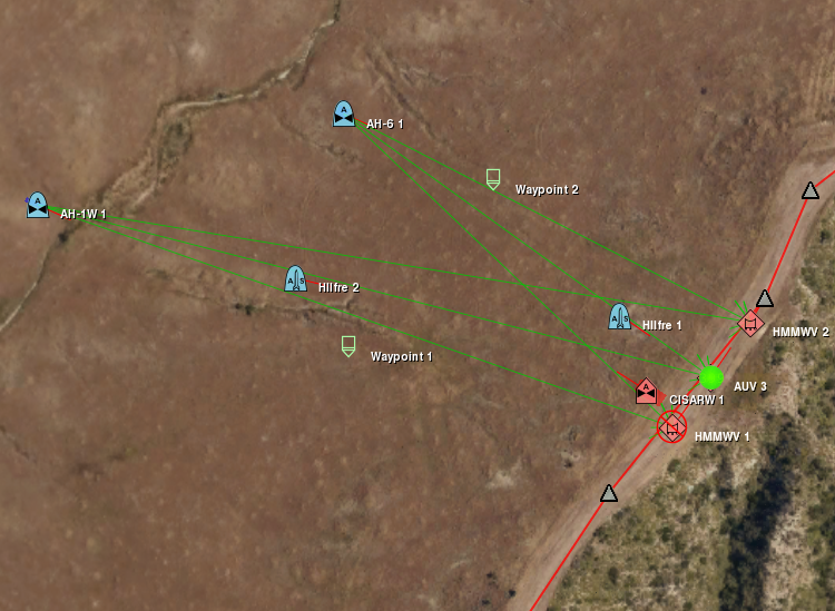
- Radar Coverage - VR-Forces can display the area in which a simulation object’s radar can detect objects.The radar coverage area is color coded based on the altitude at which it is testing intersections. Each color shown indicates full visibility at that altitude and above.

Sound Effects
Like visual graphics, sounds provide information about the simulation. VR-Forces plays sounds based on the proximity to a selected entity. Default sound mappings are included in the VR-Forces entity definitions and you can remap these with your own sound files as you see fit.
Time Management
Scenarios run in simulation time. Simulation time can be mapped one-to-one with wall clock time or it can run slower or faster than real time.
The simulation time can be changed through the Time Multiplier toolbar in the GUI, or programmatically through the APIs, even while the simulation is running.
Real-Time and Post-Simulation Analysis
As a VR-Forces scenario runs, you can view it in the VR-Forces GUI as the action unfolds and take advantage of various information panels for immediate understanding of simulation object behavior. If VR-Forces is participating in a distributed simulation, you can see its effect in the other simulation participants, such as IGs or other simulation federates. (VR-Forces distributes the simulation activity using industry standard simulation protocols, specifically the high level architecture (HLA) and distributed interactive simulation (DIS). And, of course, you can use the MAK Data Logger to capture the entire simulation (your VR-Forces action and the rest of the distributed simulation) and record it to a file for replay and further analysis.
Modeler – Configure, Customize, and Script
The VR-Forces Modeler is a person who can use VR-Forces out-of-the-box (no C++ programing required) to configure VR-Forces for the specific simulation needed by an organization.
- Simulation Object Editor – Since simulation objects are the basic units of the simulation, VR-Forces provides a Simulation Object Editor with a graphical user interface so you can edit the simulation objects that come with VR-Forces, create new simulation objects by reconfiguring the models, attributes, and resources of an existing simulation object, or create entirely new simulation object types.
With the Simulation Object Editor you can easily compose simulation object definitions – assign simulation models, such as weapons and sensors, to simulation object types, modify parameters for each simulation object type, including top speed, top acceleration, and top deceleration (braking), turning radius, type and amount of ammunition, and bounding volume, associate simulation objects with 2D icons and 3D models for visualization, and much more.
- Simulation Model Sets – The specific capabilities of simulation objects are defined within simulation object definitions, which are organized within simulation model sets. VR-Forces comes with two pre-defined simulation model sets: an aggregate-level SMS, which defines aggregate level simulation object models, and an entity-level SMS, which defines entity level models (platforms, humans, units, and munitions).
- Object Parameter Database – VR-Forces stores default configuration data for all simulation objects and tactical graphics in the object parameter database. When a simulation object or object is added to a scenario, it is created with the capabilities defined for that object type. The data is stored in configuration files that you can edit using the Simulation Object Editor.
Organize Simulation Objects
Simulation objects simulated by VR-Forces exist in the context of a hierarchy. At the top-most level, simulation objects are grouped according to force ID (friendly, opposing, neutral, and so on). At the bottom-most level are individual simulation objects. Each level of the hierarchy is called an echelon and each simulation object can be identified by its designation within its echelon.
When you create a new simulation object, it is a member of a force. VR-Forces supports upto 255 unique force types, so you have plenty to model allied forces, opposing forces, any sorts of neutral forces (civilians, police, protesters, and so on). An aligence matrix describes which forces are hostile or neutral to the others, giving you complete freedom to describe the relationships. As you aggregate simulation objects into organizational units, such as platoons, companies, and so on, their echelon ID expands to encompass each level of the hierarchy.
Merge Scenarios
Complex scenarios for large simulation are often built by multiple teams rather than one individual. VR-Forces supports collaborative scenario building using the scenario import feature. Scenario developers can create portions of a master scenario and then easily import them into the master. VR-Forces uniquely identifies every simulation object so that there are no conflicts.
Configure Terrains
Our philosophy at MAK is to make our tools Terrain Agile, which means that we strive to support most terrain formats and make it easy to create the terrains you need with the data you want to use. Combine your source elevation data, imagery, and feature data to create high quality terrains. Then save them in MAK Terrain Format (MTF) for quick reloading. To stream large amounts of local data or to connect to dynamic terrain servers, like VR-TheWorld Server, use the osgEarth .earth format. These files provide the instructions for how VR-Forces will interpret the streaming terrain data and internally construct the terrain definition to simulate on.
Script Behaviors with the VR-Forces Behavior Engine
VR-Forces has a built in Lua language interpreter and Lua bindings for building higher level behaviors. Lua is a popular scripting language used largely in gaming systems to give simulation objects intelligent behaviors that are triggered by the simulation surroundings and events. Lua scripting allows modelers who have programming skills to create new tasks for simulation objects and add them directly to the VR-Forces menus where they are applied just like any tasks that were delivered with VR-Forces.
- Scripted Tasks - Scripted tasks can be added to the task menus and used in plans just as the built-in tasks. The scripted task process automatically creates a dialog box to accept user input for the task.
- Reactive Tasks – Scripted tasks can be reactive – they can be assigned to simulation objects of a specified type and designed to react to conditions within the simulation. Multiple reactive tasks can be assigned with given priorities to enable simulation objects to react to complex situations. Reactive tasks cause simulation objects to temporarily suspend their previous actions, and then return to those actions once they have completed a reaction.
- Scripted Sets - Similar to scripted tasks, you can add new set data requests to the set menus and plans. Like built-in sets, scripted sets do not interrupt an entity’s task.
- Behavior Sets – Scripted tasks can be organized into behavior sets and applied to simulation objects as a function of their “force” value. In this way, sets of behavior can be designed to support the doctrine of different forces so that like simulation object types will behave differently according to their doctrine. Behavior sets can be exported, shared, and imported with other users to enhance collaboration.
For more information about Lua scripting, read our white paper.
Developer – What You Can Do if You're a Programmer
VR-Forces is useful for many simulation tasks straight out-of-the-box and modelers can configure it to suit their custom needs. But VR-Forces is also a well designed software developer toolkit. It is made to be extended with new functionality and customized to fit into your simulation architectures, even embedded directly into your training and experimentation systems.
Component Architecture
The behavior and dynamics models in VR-Forces use a component architecture similar to that used in many robotics applications. There are three basic types of components supported: sensors, controllers, and actuators. Components communicate with each other through data ports, which may provide data as simple as a single number, such as a throttle value, or more complicated data, such as a list of entities that have been detected. The component architecture supports any number of sensors, controllers, and actuators in a simulation object. Many components are included in VR-Forces, but new ones may be written in C++ and added through the plugin API.
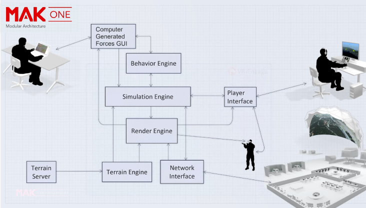
- Sensors – Sensor components provide models of the simulated environment that are then used by controller components to make decisions and perform tasks. The simplest sensor might provide (simulated) ground truth, while more sophisticated ones could use complex models for IR sensing, RADAR, or a cognitive model to simulate a soldier or crew member's perception of the simulated world. Sensor components may get information from the virtual network (through a VR-Link exercise connection and Reflected Entity List), from a terrain database, by monitoring the state of the simulation object model itself, and many other potential sources. VR-Forces simulation objects are configured with visual, radar, sonar, and infrared sensors, as appropriate.
- Controllers – Controller components use the information provided by sensor components to perform specific tasks. The task or tasks to be performed are communicated via a radio-like message system. Given a task to move to a waypoint, for example, an automotive controller might take terrain input from one sensor, a list of close obstacles to avoid from another, and feedback about the simulation object's current state (speed, heading, and so on) from still others. Using this information, the controller could calculate, for each frame, steering, throttle, gear, and brake settings to get the simulation object to the waypoint without colliding with any other obstacles.
- Actuators – Actuator components provide the physical model of the simulation object being simulated. Actuators are the components that make changes to the simulated environment. They use control inputs provided by controller components as parameters to its model each simulation frame. Actuators may send messages on the radio system, generate events on the virtual network, such as detonations, and modify the state of the simulation object simulated: position, velocity, damage, and so on.
APIs
The APIs (application programmer interfaces) that MAK engineers used to build VR-Forces are available to you as well. The standard VR-Forces applications, the front-end/GUI and the back-end/simulation engine, are built using the VR-Forces APIs. The front-end is built using the GUI API (which is based on the VR-Vantage Toolkit). It uses the Remote Control API to send control messages to the simulation engine. The back-end is built using the Simulation API. Both use the Terrain API.
The following figure illustrates how the VR-Forces APIs are used in the VR-Forces executables.
- Simulation API – The Simulation API is usedto customize or extend the simulation engine (a.k.a. back-end). VRF provides simulation models of many different types of simulation objects. You can add more and/or override the behavior of existing simulation objects using the Simulation API.<br\>
- GUI API – The GUI API is used to customize or extend the front-end graphical user interface. The VR-Forces Graphical User Interface rendering is based on the VR-Vantage Developers Kit. The VR-Vantage libraries and header files are included with VR-Forces and a VR-Forces developers license includes the ability to use the VR-Vantage developers kit to modify the VR-Forces GUI. The VR-Forces GUI API uses Qt - an open-source, cross-platform GUI development toolkit.
Non-developers can modify the menu structure and dialog box details by editing configuration files.
- Remote Control API – This is the API used to send control messages to the back-end simulation engine from other applications. The VR-Forces front-end uses the VR-Forces Remote Control API to control the back-end application. The Remote Control API is also meant to be used in custom VR-Forces front-ends, simulation managers, or Instructor/Operator Stations.
When you use the Remote Control API, you do not need to worry about the details of the network messages being exchanged between your application and the VR-Forces simulations. These are handled transparently. On the other hand, the API provides access to these messages, so that you can extend or modify the way the Remote Control API communicates with VR-Forces simulation engines if you need to.
- Terrain API –This API reads, writes, and queries the terrain for collisions, or intersections. The VR-Forces GUI uses the terrain API to access the geometry and vector data it needs to display the terrain data. The VR-Forces simulation engine uses the terrain API to perform terrain intersection tests for modeling ground vehicle movement, to query the terrain’s vector network for roads to follow, S57 depth values,and line of sight in its sensor model.<br\>
- Plug-in API – The Plug-in API lets you add functionality to VR-Forces or modify existing functionality without rebuilding the core VR-Forces applications. You can extend much of the vrfSim application using plug-in DLLs. The plug-in interface gives you access to: vehicle dynamics, control objects, sensors, controllers, weapons systems, radio networks, terrain representation, coordinate conversions, network messages, tasks, and plans. For example, if you want to add a new toolbar and an unrelated new menu command, use separate plug-ins. However, if the new features work together, such as a new menu and a toolbar with icons for the same set of features, use one plug-in.
Localization
Because the VR-Forces graphical user interface is built using the Qt GUI toolkit, it benefits from Qt’s support for localization. You can translate all menu and dialog box text using the Qt Linguist utility, which is shipped with VR-Forces. We also include the translation files from which you can translate GUI text to your local language. Chapter 2 in VR-Forces User’s Guide explains how to use the Qt Linguist utility to localize your copy of VR-Forces.
Compelling Content and Graphics – Simulation Objects, Terrain, and Dynamic Environments
VR-Forces is loaded with content. Out-of-the-box you get hundreds of simulation object definitions preconfigured and ready to use in a simulation. You get hundreds of 3D models mapped to entities for 3D visualization. You get several useful terrain databases that you can use as the basis of your simulation exercises; hundreds of human characters used by the embedded DI-Guy capabilities; software effects for the environment, weather, and dynamic special effects; and last, but certainly not least, you get a rich set of documentation covering all aspects of the product and its use.
Simulation Objects
Representations of simulation objects include:
- Simulation Models– Large library of simulation objects available for your use in developing rich air, land, sea, and space scenarios.
- 3D Graphic Models – Large library of 3D representations that map to DIS/RPRFOM object types for use by your scenario and reflecting the state of the other simulation objects distributed across the federation. Iconic 3D models are available for each domain of simulation objects so you can have something in 3D for every entity type.
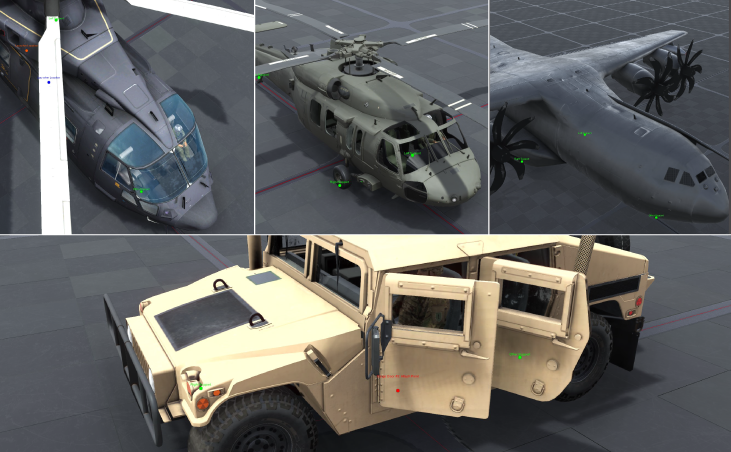
- XR Models – Symbolic 3D models to see entities at great distances in 3D exaggerated reality modes.
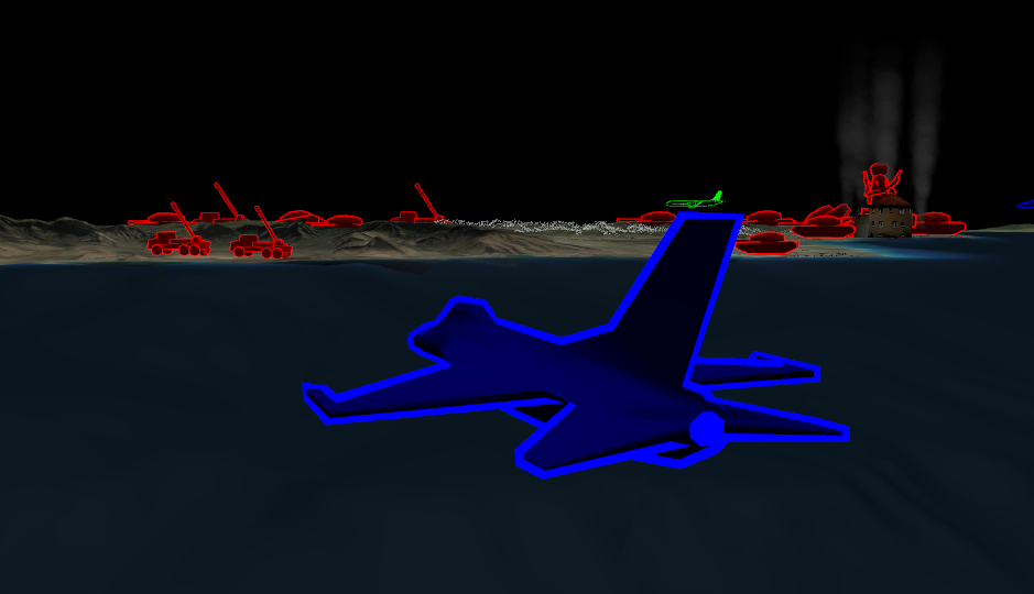
- Map Icons – MILSTD 2525B map icons used to easily identify simulation objects by type and capabilities.
Human Characters
VR-Forces uses MAK’s DI-Guy SDK to provide a rich set of human characters with multiple appearances, heads, weapons, and animations. Animals too.
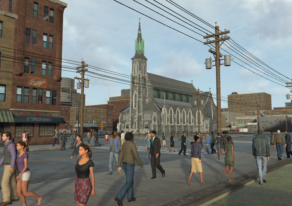
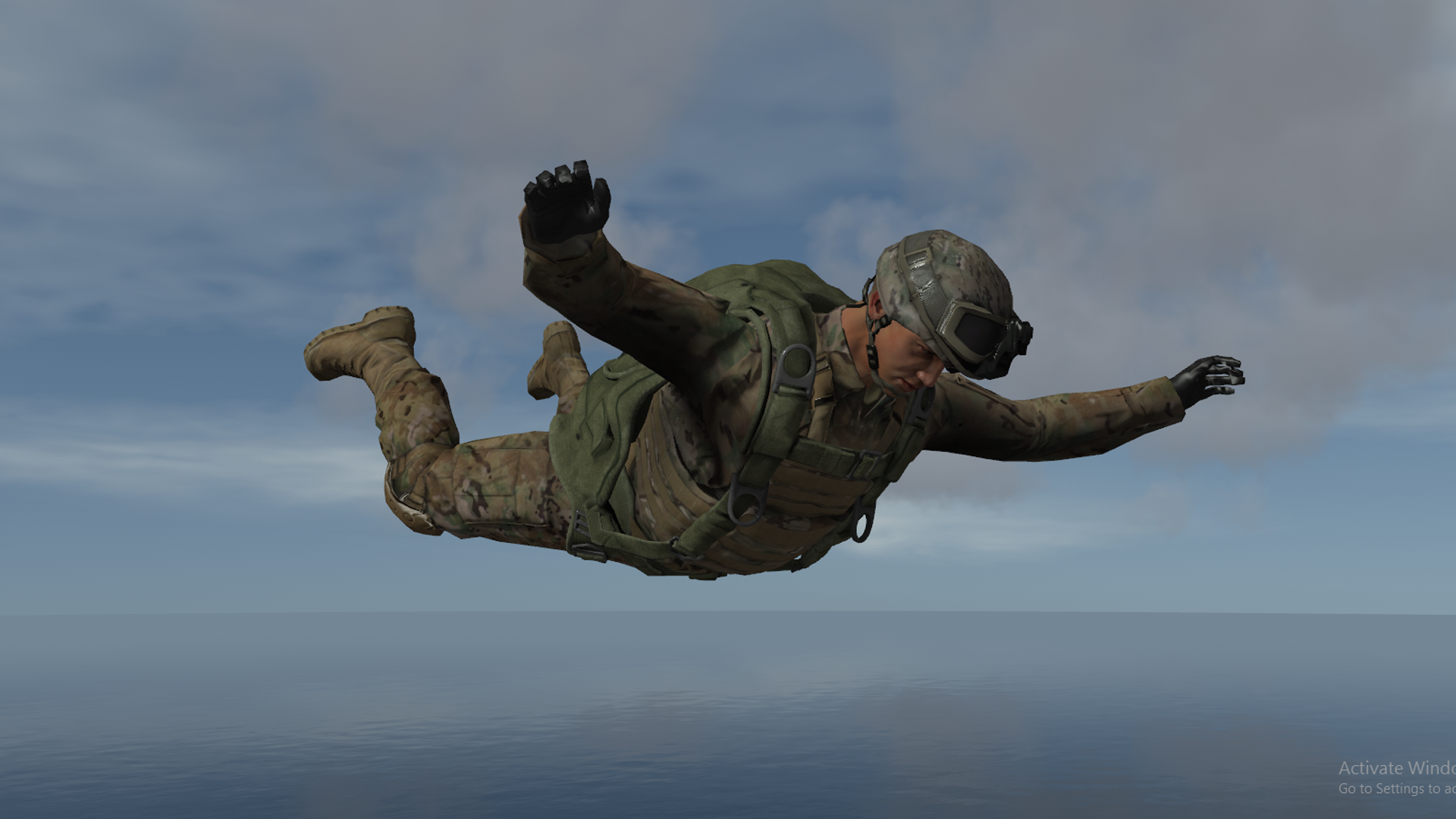
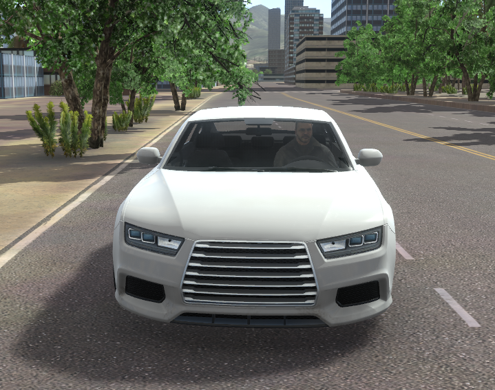
If a vehicle has interior geometry, VR-Forces can automatically put a human character in the driver's seat. These characters are not simulated as individual entities. They are strictly for visual effect. You can disable human occupants when you want a simulated entity to embark in a vehicle.
Terrain
VR-Forces is Terrain Agile. That means that it can use many terrain formats and terrain loading strategies. You can even mix and match terrain of different types to compose your own terrain for simulation.
VR-Forces accepts terrain in the following database formats:
- Streaming Terrain – Using OSG Earth, VR-Forces can accept streaming GIS data using OSG and OSGeo standards: WMS (Web Mapping Service), WFS (Web Feature Service), and TMS (Tiled Mapping Service).
- Static Terrain – Loading terrain databases and site models in many formats, including OpenFlight, 3D Studio (3ds), Collada (DAE), Lightware (LVE), and OpenSceneGraph formats.
- Paging Terrain – VR-Forces supports the MetaFlight, Terra Page, and Pageable IVE formats.
- Procedural Terrain –
- Imagery and Raster Maps: CADRG, Geotiffs, and many more.
- Elevation Data: Digital terrain elevation data (DTED)
- Feature Data: ESRI's shape file format (shp), DFAD, DFD, VPF
- Legacy SAF terrain formats –GDB, CTDB format (.c4b, .c7b, and .c7l versions)
- Composeable Terrain – Terrains of many formats can be combined to compose a unique terrain that meets your specific needs. Sites can be cut into terrains of other formats and 3D models can be added via configuration files or even interactively within VR-Forces GUI.
- Shapefile Export and Import – VR-Forces can export tactical graphics to shapefiles, which you can then use to build more complex terrains. It can also export and import props and SpeedTrees.
Dynamic Terrain
VR-Forces supports dynamic destruction of terrain using switch nodes in OpenFlight models. Terrain state can change as the result of munition damage or by direct manipulation by a VR-Forces user. It also supports non-destructive model changes, such as opening doors and windows. Entities can open and close doors and windows using appropriate tasks, which means these behaviors can be added to plans.
Contact us for help if you require different approaches to dynamic terrain.
Embedded Cultural Features
If you place a cultural feature, such as a building, that has object geometry, VR-Forces can treat that object as part of the terrain. This means that entities can walk on it or in it (if it has interior geometry).
Useful terrain databases included:
VR-Forces comes with several terrain databases that you can use in your projects:
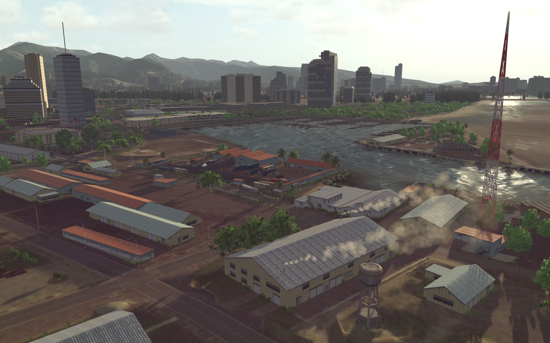
- Hawaii – A rich and beautiful example of a composable terrain that includes streaming terrain, cut in sites, and prop models. Hawaii is available online from VR-TheWorld Server. But since many of our customers do not have access to the internet, we install a subset of Hawaii that can be run locally with VR-Forces.
California – Worldwide terrain, but with detail in Southern California, particularly around Camp Pendleton.
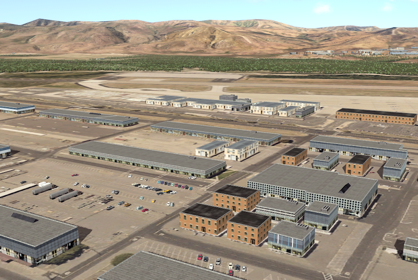
A supplemental data package is available for VR-Forces (and VR-Vantage) that adds even more useful terrains.
- Brooklyn – This is a composite terrain consisting of the DI-Guy Stage 12 site model that has been well positioned within a section of Brooklyn New York. The area surrounding the site is streamed from a disk cache or VR-TheWorld Server.
- Peter’s Pond – This is a hand modeled site that includes a lush example of high density vegetation using SpeedTree trees.
- Driving Town Day – Developed and sold by B-Design, Driving Town Day is a terrain suitable for urban driving simulators. It offers a wide selection of roads and complex intersections. Many roads are covered in speed trees with pedestrian crosswalks, sidewalks, and different parking configurations. This database may be used “as-is” inside VR-Forces simulations. A non-watermarked version can be purchased form B-Design.
- Driving Town Night – Developed and sold by B-Design, the Driving Town Night is the same terrain as Driving Town Day, except emissive textures have been added to provide beautiful low light visualization. Street lights cast light on the sidewalks, and store fronts illuminate the scene. This database may be used “as-is” inside VR-Forces simulations. A non-watermarked version can be purchased form B-Design.
- Middle Eastern Village – Developed and sold by B-Design, the Middle Eastern Village terrain is a large terrain suitable for air and ground operations over a sprawling Middle Eastern village. The village is surrounded by fields and forests allowing for a wide variety of training operations. This database may be used “as-is” inside VR-Forces simulations. A non-watermarked version can be purchased form B-Design.
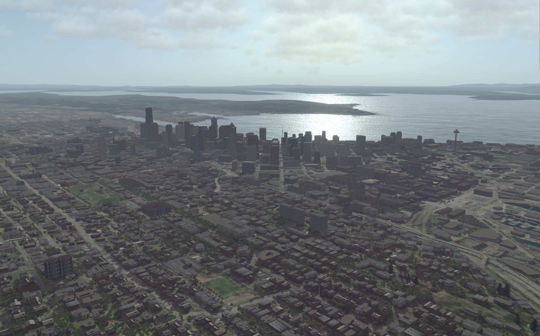
- Emerald City – MAK VR-TheWorld server data merged with US Army sample SE Core data for Emerald City. The SE Core sample data is provided for free, with Distribution A (Approved for public release: distribution unlimited) rights. Point trees from the Seattle Open Data Portal (https://data.seattle.gov). SE Core data includes feature data for buildings, cranes, shrubs, flagpoles, communication towers, roads, sidewalks, and water areas. Also included in the terrain is a generic procedural image layer and geospecific and geotypical building models provided as OpenFlight.
Dynamic Environment
Much of the simulation environment is loaded as terrain, but there’s a lot more that is generated procedurally in the form of the atmosphere, dynamic water, weather, and lighting.
Dynamic Ocean
VR-Forces has beautiful, accurately rendered, 3D oceans that affect the rocking of ships in 3D scenes.
VR-Forces provides dynamic ocean visualization in the 3D scene mode. The ocean shows waves, swells, and spray effects. Surface entities have realistic wakes and buoyancy behavior. MAK uses customized technology from our partner, Sundog Software, to model the ocean surface.
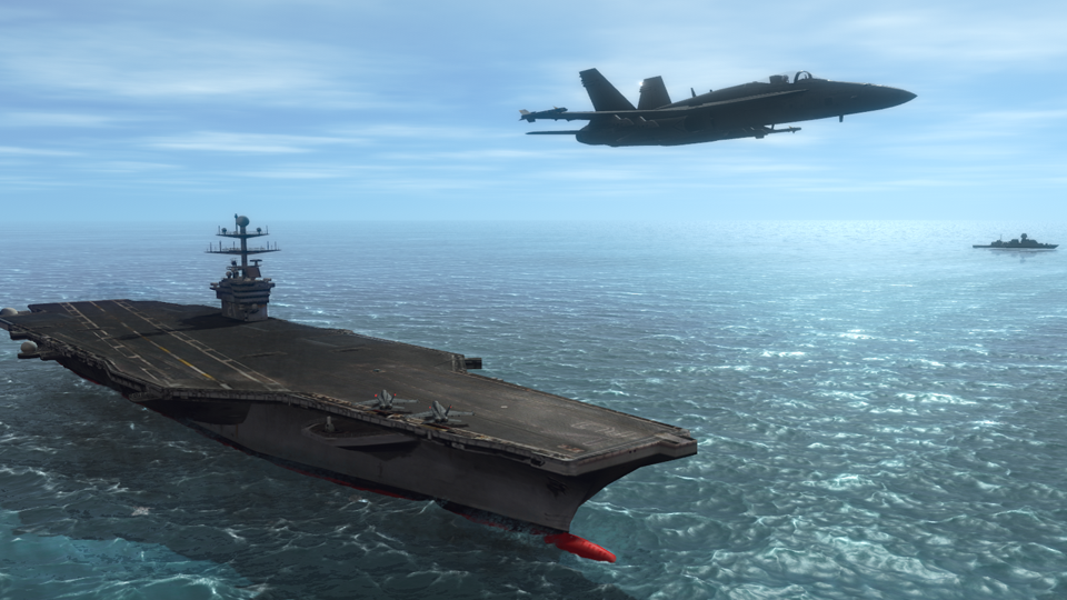
The visual transparency—the ability to see through the water from above sea level—of the surface can be user controlled. Separately, thermoclines can be defined that will affect the ability of the sonar sensor model to “see” entities under the water. Surge depth lets you calm shallow water to visualize offshore wind and calm harbors.
Radiometrically Accurate Atmosphere & Lighting
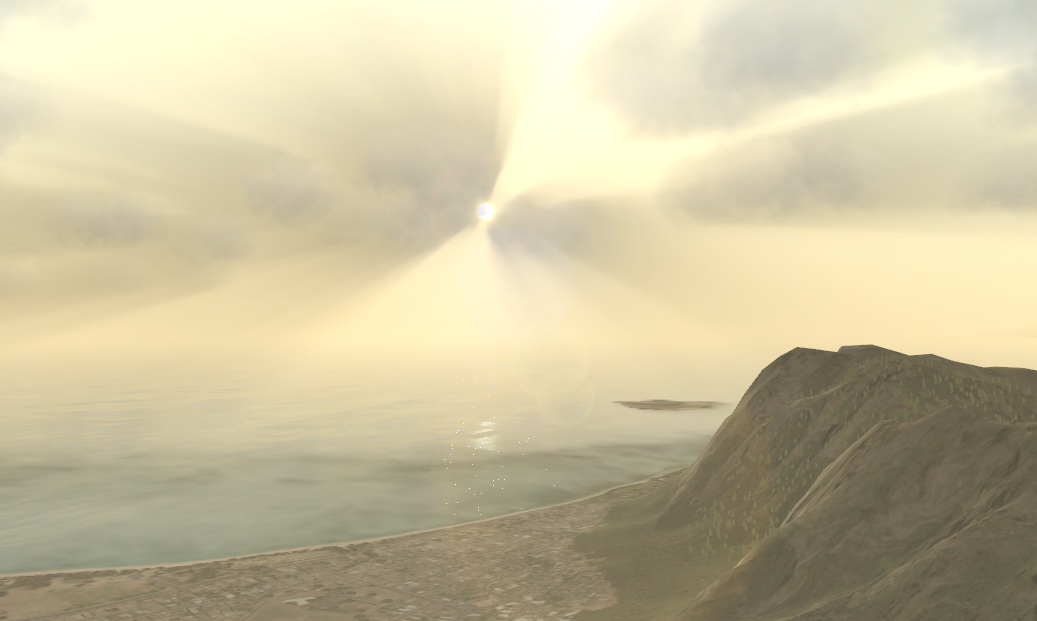
VR-Forces has beautiful, accurately rendered, sky, clouds, rain, snow, sun, moon, and stars. The visibility can be set to affect both the visual appearance, and the sensor model’s ability to detect simulation objects. Separate visibility parameters control the visibility underwater.
VR-Forces supports high dynamic range (HDR) lighting for even more realistic scenes.
Weather
Precipitation type (rain, snow, hail, sleet, drizzle) causes visual rendering effects and modifies the sensor model’s ability to detect simulation objects. Changes to wind speed and direction affect wave action, cloud motion, and the drift of tactical smoke, sand, snow, dust, and so on.
Date and Time
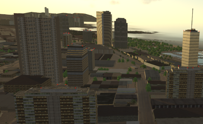
VR-Forces uses a full-year ephemeris model that changes the position of the sun and moon as a function of date and time of day. The simulation time triggers an appropriate change in the visual scene and affects the sensor's ability to detect simulation objects.
Interoperability – DIS and HLA
VR-Forces interoperates as part of a simulation federation, of course. You shouldn’t expect anything less from MAK, the pioneers of COTS interoperability tools for HLA, DIS and other protocols.
DIS/HLA (user)
- Easily connect to DIS and HLA exercises – The VR-Forces Launcher provides configurations for the most common DIS and HLA RPR FOM connections, including HLA 1.3, HLA 1516, and HLA Evolved and support for the DI-Guy FOM extensions. Easily create your own configurations. Since VR-Forces uses VR-Link for its networking, it is FOM-agile.
- Knowledge of all the simulation objects and interactions in the federation – VR-Forces not only publishes simulation objects to the network, it can also work with simulation objects simulated by other federates. Other federates can simulate the complete simulation object, or part of the simulation object such as an emitter track/jam beam.
Examples and Documentation
VR-Forces comes with a complete documentation set.
- First Experience Guide – Instructions for seeing results in the first five minutes of use.
- Users Guide – A comprehensive manual that covers all aspects of creating scenarios, using the GUI, loading and editing terrains, and configuring both visual models and simulation models.
- Adding Content to MAK Applications – Instructions for how you can add your own simulation object models and terrains to MAK applications.
- Developer’s Guide – High-level concepts for API users. It is augmented by more than 40 example projects containing source code and modified support files (simulation object models, object parameter database, terrains, and so on.) Includes class documentation.
- Entity Model Catalog – An illustrated catalog of all simulation objects included with VR-Forces.
- VR-Forces Release Notes – How to upgrade from older versions of VR-Forces.
- Users Migration Guide – Instructions for migrating from an older version of VR-Forces to the next version.
- Online help – An HTML5 version of the Users Guide and Adding Content to MAK Applications Manual.
